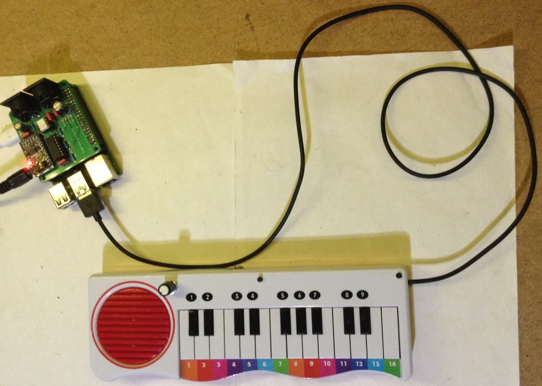
So this follows on from the first part and adds MIDI, some buttons to control the keyboard and gives it a voice of its own.
Warning! I strongly recommend using old or second hand equipment for your experiments. I am not responsible for any damage to expensive instruments!
If you are new to microcontrollers, see the Getting Started pages.
Parts list
- Cheap, recycled toy keyboard.
- Raspberry Pi Pico
- Push buttons
- 3.5mm TRS socket (chassis mount)
- Optional: 220Ω resistor; 10kΩ potentiometer; NPN transistor (e.g. 2N2222A)
- Jumper wires
The Circuit

There are four distinct functions that I’ve added to the keyboard, so I’ll take each in turn. Recall that the Pico is also connected to the keyboard matrix as described in part 1.
MIDI OUT
I’ve used a version of my 3.3V MIDI OUT circuit for the Raspberry Pi Pico and connected it to a 3.5mm TRS socket. I’ve linked it up to GP0 (TX).


I’m using the later-standardised version of MIDI TRS as described in my MIDI Connections Cheat Sheet. This means I can use my home-made MIDI TRS to MIDI DIN cable to link up to other modules, such as my Zynthian as shown here. The keyboard still requires power over the USB link to use serial MIDI.

Audio (PWM) Output
The keyboard has a built-in speaker, so I’d really like to use it. I’ve configured it for a PWM output on GP2. There are several options that I’ve considered:
- Hook it up directly to an IO pin and drive it with PWM audio.
- Use the recommended Pico audio output circuit.
- Hook it up to an off-the-shelf amplifier module.
- Use a common “small signal amplifier” transistor circuit.
- Fudge some kind of random transistor circuit together…
The first is the simplest and does appear to work, but I’m a little unsure about driving a speaker directly from an IO pin without any kind of additional resistor in place. With the 8Ω speaker built into the module, the worst case current at full 3V3 would be 3.3 / 8 which is more than 400 mA which would be way too high (potentially almost 30 times too high) for an IO pin. Now I’m planning to put out a waveform driven by PWM so the actual current will on average be a lot lower (RMS voltage levels need to come into play at some point) but even so, a resistor is a sensible precaution. But adding any useful resistor significantly reduces the amount of output power available for the speaker. So some kind of amplification would be really advantageous.
Section 3.4.1 in the the official “Hardware Design with RP2040” guide has a circuit for PWM output. But it isn’t designed to drive a loudspeaker, it is designed for either headphone or line level output, so that isn’t particularly helpful to me here.
I have a number of cheap off-the-shelf amplifier modules, some are “class D” amplifiers which use PWM as an amplification technique, but I’m not quite sure how a PWM input signal would interact with a PWM amplifier. So I tried one of my LM386 based amplifier modules, and that did largely work. I powered it from VBUS on the Pico, which gave it 5V to work with. The result was quite noisy though, even after tuning with the onboard trim-pot. Also I wasn’t sure if I could add any kind of volume control, so again I thought I’d try something else.
Ideally I’d have some basic amplification using a few components, and the canonical “simple” amplifier circuit is the transistor-based small signal amplifier. There is a great explanation of how to design them and how they work here. I managed to get something sort of working, but I just couldn’t seem to get any kind of useful gain out of it and my electronics knowledge just isn’t up to knowing quite how to make this work properly for my circuit.
Ultimately all I really wanted was a way to drive the speaker that didn’t involve drawing much current from the IO pin. In end I found a simple transistor circuit that apparently has been used with a range of embedded controller PWM demonstrations as a “speaker driver”, so I went with a variant of that.

Notice that I’ve added a potentiometer to act as a kind of volume control. When fully turned in one direction, the base of the transistor is effectively at GND (0), albeit still via a 220Ω resistor. When fully turned in the other direction the base will be almost at full voltage of the input – it is a potential divider with resistor values 220 and 10,000, which means around 98% of the input voltage reaches the transistor.
Note that there are lots of things wrong with this circuit and any proper electronics person is probably wincing at this point (assuming they haven’t clicked away in disgust!). I know enough about how it is working to know the following (but not really enough to know how to fix it):
- The input to the base transistor isn’t biased to work around the right operating voltage for the transistor, so there will be “clipping” happening at the lower voltage levels.
- There is no coupling capacitors anywhere so there are probably currents going in all directions competing with each other for the final output signal.
- The current through the loudspeaker could still, in theory, reach the aforementioned maximum of ~420mA. Actually, its worse than that – I’m powering it from VBUS on the Pico which is the USB 5V supply, which means it could in principle get to 625mA if it was a sustained DC 5V. USB 2.0 “high power” devices can pull 500mA IIRC. This is a waveform though, so we’d probably need to use an RMS value, but this is getting outside of my knowledge again. It might be prudent to add an additional 10Ω resistor to limit current further – see how you go – but remember the warning – don’t plug it into your expensive laptop or music equipment to experiment!?
- I have limited the current from the IO pin though. At minimum resistance, when at volume “0” with the pin connected to ground, it is still going through a 220Ω resistor, so giving us 15mA at 3.3V to ground. I think that is fine for the Pico? I’ve seen 16mA each and 50mA total mentioned on the forums, but haven’t found what seems to be any kind of authoritative source on the matter. It seems very hard to find any kind of official statement on the current limits of the Pico’s power and IO pins!
- There is now PWM filtering or smoothing going on. The PWM carrier frequency seems too high to be of real concern, so I’m not worrying too much about it.
- Finally, to be perfectly honest, I have no idea what the gain of the amplifier is here, and I’m guessing it is totally dependent on the built-in resistances in the transistor (and probably a whole host of other things too). So it is quite easy to have a distorted or clipped signal when everything is too high.
The real way to solve these issues is to build a proper small signal amplifier circuit as mentioned previously. But also as mentioned previously, I don’t really know what I’m doing…
A really simple safeguard is to use one of those “USB current” measuring devices (assuming you can trust such a cheap device) whilst plugging it into a (potentially) sacrificial USB power source (i.e. not your PC or expensive music equipment!). In my case it never seems to register a current draw on the USB port of more than 130mA (this was at full volume, playing a square wave tone) so I’m working on the assumption that I’m probably ok.

For my own part, from experimenting, given all the above constraints, actually I think the results don’t sound too bad. At the end of the day, this is a cheap, 8Ω small speaker, in a toy keyboard that was found on the front of a children’s book!
Here are some photos of the speaker circuit. First are two experiments – a direct IO pin connection and a solderless breadboard simple transistor circuit, just to get started.


And here is the final circuit in situ. As you can perhaps see, I’ve soldered two legs of the transistor directly to the connection tabs of the potentiometer, and the other to the speaker. The third tab of the pot connects via the 220Ω resistor to the IO pin and the other speaker connection goes off to VBUS (i.e. 5V) on the Pico.
The potentiometer pokes through the casing right next to the speaker. I had to trim off part of the (apparently) unused red speaker mounting to get it to fit nicely.

Selection Buttons
I’ve added two buttons, both to be used in INPUT PULLUP mode for various functions. These are connected to GP3 and GP4. Each button has a connection to an IO pin and GND.


One of the buttons pokes through the casing right in the corner as shown above. Notice how I’ve crudely ensured it is fixed in using hot-glue! The other pokes through next to the MIDI socket and again is fixed using hot-glue. I’ll have to see how long they last with continued pressing…

The Code
The functionality I’ve gone for is as follows:
- GP0 – TX for MIDI OUT connection.
- GP2 – PWM audio output via the simple amplifier and volume control potentiometer.
- GP3 – Switch in pull-up mode, to select different waveforms for the PWM output.
- GP4 – Switch in pull-up mode, to change the octave.
In terms of generating a PWM waveform from Circuitpython, there are a few tutorials out there that might help:
Some initial confusion comes from the fact that there appear to be two “audio io” standards in use at present. Some boards seem to support “import audioio” and some need to explicitly use “import audiopwmio“. The Pico appears to be one of the latter, whereas many of the examples I found for the CPX appear to use the former – Kevin J Walters seems to have rather a lot of examples for the CPX!
My starting point was to create a Pico version of the “cpx_basic_synth.py” example. This involved doing the following:
- Switching from audioio to audiopwmio.
- Removing the neopixel code.
- Removing the code to enable the speaker (mine is always on).
- Removing the code for pitch bend and modulation (I just want simple tone generation for now).
This allowed me to test the basics – USB MIDI generating a simple tone. From this starting point I was able to then add PWM audio functionality to my code from part 1.
I generate three waveforms and then select them based on a value controlled by the “waveform button”.
def sawtooth(angle):
  return 1.0 - angle % twopi / twopi * 2

def square(angle):
  if angle < math.pi:
    return 1.0
  else:
    return -1.0

w_saw = array.array("H", [0] * sample_len)
for i in range(sample_len):
  w_saw[i] = int(sample_bias + round(32767 * sawtooth(math.pi + twopi * (i+0.5) / sample_len)))
w_sin = array.array("H", [0] * sample_len)
for i in range(sample_len):
  w_sin[i] = int(sample_bias + round(32767 * math.sin(twopi * (i+0.5) / sample_len)))
w_squ = array.array("H", [0] * sample_len)
for i in range(sample_len):
  w_squ[i] = int(sample_bias + round(32767 * square(twopi * (i+0.5) / sample_len)))

#for i in range(sample_len):
# print (w_sin[i])

wave = []
wave.append(audiocore.RawSample(w_saw, sample_rate=sample_rate))
wave.append(audiocore.RawSample(w_sin, sample_rate=sample_rate))
wave.append(audiocore.RawSample(w_squ, sample_rate=sample_rate))
That commented out for loop and print statement outputs the values in the generated tables. When put in a spreadsheet and turned into a graph, they look like this:

I’ve written dacNoteOn() and dacNoteOff() functions to start and stop the PWM output in response to a MIDI note messages.
The switch handling takes place in the main loop. Here is the code to change the waveform used.
if not wavsw.value:
  sample_wave = sample_wave + 1
  if sample_wave > len(wave):
    sample_wave = 0
  time.sleep(0.2)
In case you’re wondering if there is an “off by one” error here, there isn’t as sample_wave = 0 means “no wave”. From the previous code, you can see that the three waveforms are wave[0], wave[1], and wave[2] so when it comes to actually picking the wave to play in dacNoteOn() I have to use:
if sample_wave != 0:
  wave[sample_wave-1].sample_rate = note_sample_rate
  dac.play(wave[sample_wave-1], loop=True)
It isn’t, perhaps, the most obviously maintainable code, but it will do for me in this application. No doubt this sentence will come back to haunt a future me when I change something and forget I did this!
In terms of handling the changing octave, I simply maintain an “octave number” that is updated by pressing the button and add that in (multiplied by 12) when calculating the MIDI note number corresponding to a key being pressed.
noteOn(firstnote + n + octave*12)
“firstnote” is the start of the keyboard – I’m using G2 which is MIDI note 43; “n” is the index into my keyboard management array that maintains which keys are pressed and released; and “octave” is the octave number: from 0 to however many I decide to support. I’ve chosen to use the following:
- 0 = G2 (43)
- 1 = G3 (55)
- 2 = G4 (67)
- 3 = G5 (79)
Remember this is the mapping for the lowest note on the keyboard, so the highest note it will be able to play will be F7 (101).
Closing Thoughts
I wish I understood the electronics theory a little better to know how best to solve the audio output problem, but the solution I have seems to work, from experiment and measurement, ok.
There are two ways to get it back to “MIDI controller mode only” – either simply turn down the volume(!) or select “wave 0” mode.
I could keep adding features, but eventually I’m going to run out of physical space. I’ve still only used one side of the Pico’s IO!
One thing I could do now though is try some more complex waveforms. At present I calculate three common patterns, but there are many others that are easy to calculate too – a triangle is the obvious one missing, but also some pulses might be fun to try.
But ultimately I’m just playing a wavetable, so it could have any sound in there that could fit! For a more complex sound thought, I might need to increase the number of samples.
At present it is 256 16-bit samples though, so I could probably get quite far just with that!
Kevin