Ok, I admit, there is a bit of a theme to some of my projects, but this keyboard that I found in a charity shop was such a dinky thing that I had to do Just One More (TM).

Warning! I strongly recommend using old or second hand equipment for your experiments. I am not responsible for any damage to expensive instruments!
If you are new to microcontrolers, see the Getting Started pages.
Parts list
- Cheap, recycled toy keyboard.
- Raspberry Pi Pico
- Breadboard and jumper wires
The Keyboard
My aim here was largely to repeat my previous process:
- Take the keyboard apart to see how it works.
- Add a microcontroller to decode the key matrix.
- Add in either serial MIDI, USB MIDI or both.
- Think about what else I might be able to do.
I walked through the dismantling and thinking process in this thread on Twitter, but these photo highlight the main steps in deciding what to do with this.
The first thing, of course, was to actually get it off the book (which I didn’t want, so it went in the paper recycling) and get a look inside.


As you can see it is pretty minimal. Just a single PCB for the intelligence and keyboard and four wires – two for power and ground and two for the speaker. My initial thought was that this would be too fiddly to try to tap off the keyboard matrix, but after examining the PCB a bit more, I had a change of heart.


As you can hopefully see from my annotated version of the PCB the matrix maps out quite neatly into a 6×4 matrix. There is one curiosity though – the left-most three keys (which are the lowest three notes) don’t have their own route into the “blob” so actually it is a 5×4 matrix with three extra keys wired into the last two “rows” via a diode and resistor. This is shown in more detail below:

Initially I wasn’t quite sure what to do about this, but then I realised it was actually doing me a favour as by removing the resistor and diode I now had three very convenient pads I could solder onto to give me three of my required 10 connections to the matrix. Coupled with the fact that the pink link goes to a solder pad and the purple link is connected to ground, that gives me 5 of my required 10 connections “for free”.
To make the other connections, I scrapped off some of the protective layer in five of the wider track areas and thus gained the 10 links I need.


At this point I could add some test headers – I used “round pin hole” headers as follows.


Around about this point someone on Twitter asked about the additional “spare” pad next to the speaker output, which appears to have the solder footprint for an additional component. I speculated that it might be to allow for a capacitor for DC bias removal, but then realised I hadn’t actually looked at the original signal, so I managed to temporarily connect the wires back up to see what the original keyboard was outputting.


As you’d probably expect, it looked like it was probably some kind of PWM output swinging between 0V and 2.75V, so yes a DC bias removal option seems plausible. Other options I guess could include a second contact for headphones or a second channel (for “stereo”). It is an odd to find on such a minimalist keyboard!
My initial hope was to just see if I could drive the matrix whilst leaving the “blob” intact, but initial testing revealed that a) that wasn’t possible cleanly; and b) I’d overlooked the blindingly obvious fact that the original blob was powered from two 1.5V batteries but I would want to send at least 3.3V into it and possibly even 5V if I used an Arduino.
So in the end I cut out the blob – literally. But that left another problem. Three of the “column” connections were linked under the blob, so I had to create 6 more solder pads somewhere and add some connecting wires (which was a lot more fiddly than it should have been!).


Now I could hook it all up to a simple test circuit – a set of LEDs connected to +5V and GND via a single resistor – and check how the matrix works.

So the next step was to drop in a microcontroller and see what I could do. I opted for a Raspberry Pi Pico and decided to repeat my Toy Keyboard USB Matrix Decode with the Pi Pico.

I did wonder about using one of my smaller RP2040 devices (I still have a Pimoroni Tiny 2040 and a Feather 2040 that I haven’t done anything with yet), but I just can’t quite bring myself to solder either of those “permanently” into a project.
Then I thought I could use a “sawn-off” Pico to keep things small, but eventually I decided that actually there was no need, so “full” Pico it is then.
I’ll talk a little more about the code in a moment, but just to finish off this section, once everything was working I decided to “go for it” and solder the ribbons directly onto a Pico.
The Circuit

This is the circuit I’m planning on using. The idea is to connect up the matrix to one side of the Pico and then eventually provide the option of MIDI OUT using a MIDI TRS socket. There is plenty of IO on the other side for other things in the future too should I decide to do that.
Initially though, I’ve not soldered up the MIDI socket, I’ll get to that in a later post. This is how the Pico fits into the keyboard casing.


I “melted” a small hole in the casing to allow me to attached a mini USB cable and this is the final positioning and result.


As I say, I’ll think about adding a serial MIDI link and maybe do something with that speaker in a future project.
The Code
I’m using exactly the same code as my Toy Keyboard USB Matrix Decode with the Pi Pico. It is using CircuitPython with the Adafruit MIDI library and is full USB and serial MIDI ready. The only thing that has to change is the mapping to IO pins. My new mapping is as sketched out below.

The RBP/CY, etc correspond to the colours used in the annotated PCB photo above. The ABCD relates to the “sets of four” and the 012345 relates to the “groups of four”. The former are used as “rows” below, and latter as “columns”, which is somewhat arbitrary and opposite to how I thought of them above, but it largely doesn’t matter which way round they are.
This all leads to the following pin definitions in the code.
row_pins = [board.GP14,board.GP9,board.GP10,board.GP8]
col_pins = [board.GP12,board.GP13,board.GP11,board.GP6,board.GP7,board.GP5]
Find the original on GitHub here.
Closing Thoughts
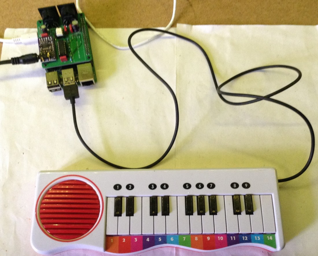
I know this is a pretty superfluous project but as a “bit of fun” I actually really like this keyboard! It is certainly my smallest “number of keys to size” USB MIDI controller! In the photo below you can see it attached to my Zynthian, fully powered over USB.
Somewhat surprisingly I found it actually supports simple polyphony. There are no isolating diodes in the keyboard so naturally I’d imagined polyphony would be problematic, but actually its not that bad for just a couple of notes 🙂
As I say, future upgrades could include adding serial MIDI and some kind of simple built-in audio output to use that speaker. One option might be a tone() output from the Pico. There is also a port of Mozzi now for the Pico, but I’d have to switch over to C (or at least Arduino C) rather than CircuitPython to do that!
Kevin

One thought on “Yet Another Toy Keyboard USB MIDI Controller”