I’ve mentioned before that I quite like some of Steve Reich‘s ideas for weird rhythms and percussion and I know thing he liked was rhythms going in and out of phase. So having just received a new bank of eight relays I thought it would be fun to combine it with my 8-pot slider board and see what I could do.
Warning! I strongly recommend using old or second hand equipment for your experiments. I am not responsible for any damage to expensive instruments!
These are the key Arduino tutorials for the main concepts used in this project:
If you are new to Arduino, see the Getting Started pages.
Parts list
- Arduino Uno
- 8 relays
- 8 potentiometers with optional multiplexer (I used my 8-way slider board)
- Breadboard and jumper wires
The Circuit

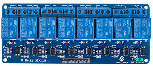
I’ve actually got an 8-way relay board like the following which is perfect for this kind of application as it only requires one set of 5V and GND connections and then just 8 IO signal lines.
In this case I’ve only used eight of the slider pots, and have hooked up the multiplexer addressing lines to A5-A2 to keep them on the same side of the Arduino. I’ve also kept four of them hooked up, even though I’m only using three to address 8 potentiometers.
I was quite tempted to try to go for 16 relays but would need to switch to a board with more IO to drive them.

The Code
The main multiplexer and potentiometer reading code is largely the same as for the previous projects.
The approach to driving the relays is as follows:
- Use the TimerOne library to set up a regular “tick” to drive everything.
- Each relay has a counter that is incremented in the “tick” function.
- When the counter reaches a specified maximum number of counts, the associated relay will be toggled and the counter reset.
- The maximum number of counts for each relay is controlled by a corresponding potentiometer.
- The potentiometers are read and handled in the main Arduino loop().
After some experimentation, I settled on a “tick” of every 2 mS. Faster than this and the tick function wasn’t able to service all relays at the same time using digitalWrite. I could optimise the code with direct PORT IO if I wanted to get more out of it, but 2mS was fine.
The pot values are used to set the number of counts (i.e. the number of 2mS ticks between relay toggles) to a value between 100 and 1123 (recall the range read from the pots is 0 to 1023). This gives me a fastest relay toggle of 100×2 mS or every 200mS – i.e. 5 every second. The slowest is 1123*2mS or around 2 and a bit seconds. But more importantly, the resolution allows for changes of the order of a fifth of a second, which allows for some great effects.
Feel free to have a play with the numbers and see how you get on.
Closing Thoughts
I really like this effect and have spent some time playing with it. Some of the best ones are when the sliders are all close to each other. It is also interesting to let them all go out of phase and then re-sync them all the same period again, but this time, whilst they are all clicking at the same rate, they are no longer clicking at the same time!
Another fun thing to do is to set the sliders then reset the Arduino. This starts all the relays off at the same time, but then they diverge quite quickly.
Next up though, I might try to do something with pitch.
Kevin
