This is the multiplexer version of my Arduino Multi-Slider MIDI Controller.
- In part 3, I extend it to 16 potentiometers.

Warning! I strongly recommend using old or second hand equipment for your experiments. I am not responsible for any damage to expensive instruments!
These are the key Arduino tutorials for the main concepts used in this project:
If you are new to Arduino, see the Getting Started pages.
Parts list
- Arduino Uno or Nano
- Up to 8 10k linear (“slider” or “fader”) potentiometers
- 42×30 protoboard
- Male and female headers
- Connecting wires
- 74HC4067 16-way multiplexer breakout board (e.g. I’m using this one from Sparkfun)
- MIDI interface with IN and OUT (for example one of the Ready-Made MIDI Modules)
- Breadboard and jumper wires (optional, not recommended)
The Circuit

The starting point is the circuit I described previously here Arduino Multi-Slider MIDI Controller.
In order to reduce the reliance on IO pins at the Arduino end, I’ve added two jumpers which can be used to pre-set the Enable pin and the last address pin to GND if required. Enable is only required if there are several multiplexers in use, and as it is active LOW, setting it to GND leaves this multiplexer enabled all the time.
There are four address bits, used to select one of the 16 inputs (0 to 15) but as I’m only using the first eight, the top bit, which would select one of 8 to 15, is always LOW. The two jumpers are situated under the module, but can be seen below.

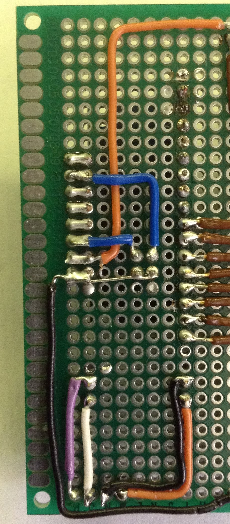
I have both jumpers enabled, so I only need three address signals to the Arduino in addition to the signal and ground.

The Code
To enable the multiplexer, the main change is an analogRead routine that will select the right pot prior to reading on the common pin.
int muxAnalogRead (int mux) {
  if (mux >= NUMPOTS) {
    return 0;
  }
  for (int i=0; i<MUXLINES; i++) {
    if (mux & (1<<i)) {
      digitalWrite(muxpins[i], HIGH);
    } else {
      digitalWrite(muxpins[i], LOW);
    }
  }

  int algval = analogRead(MUXPIN);
  return algval;
}
The IO pins to select the analog line are derived from the mux pot number by translating the binary bits associated with the pot number into binary HIGH or LOW signals for the respective pins, as shown below.
Pot   Bin   S3210
 0   0000    0000
 1   0001    0001
 2   0010    0010
 3   0011    0011
 4   0100    0100
 ...
14   1110    1110
15   1111    1111
I’ve also taken this opportunity to encapsulate the previous “nano board slider” specific analog scaling into its own analogRead variant and these are now selected based on conditional compilation at the top of the file.
#ifdef ALGMUX
#define ALGREAD muxAnalogRead
#else
#ifdef SLIDER_BOARD_NANO
#define ALGREAD altAnalogRead
#else
#define ALGREAD analogRead
#endif
#endif

...

 int algval = ALGREAD(pots[pot])>>3;
The final update is a function to initialise the mux IO pins which has to be called from the setup() routine (something I forgot to do, and left me spending an hour or so trying to work out why the mux wasn’t selecting any other inputs!).
void muxInit () {
  for (int i=0; i<MUXLINES; i++) {
    pinMode(muxpins[i], OUTPUT);
    digitalWrite(muxpins[i], LOW);
  }
}
In the actual code there is additional compilation options to support the enable pin and the actual IO pins used as the address lines are defined at the top of the file.
That is pretty much it I think.
Closing Thoughts
The multiplexer seems to be working fine. Next the plan is probably to see if I can extend this to 16 potentiometers, but I also want to start using this for other purposes related to sound synthesis too.
Kevin
