When I put together the Multi-Mode MIDI Step Sequencer it was with an eye to creating some kind of “modular” style panel format. This post documents the building of a “CDR format” (CD Rack Format) panel version.
- Part 1 (this post) details the build and testing of the panel.
- Part 2 updated and enhanced the Multi-Mode MIDI Step Sequencer code to run on the panel.
- Part 3 details the design of a panel using a PCB manufacturer.

Warning! I strongly recommend using old or second hand equipment for your experiments. I am not responsible for any damage to expensive instruments!
These are the key Arduino tutorials for the main concepts used in this project:
If you are new to Arduino, see the Getting Started pages.
Parts list
- 1x CDR format 81x250mm panel
- Pro Mega 2560
- 9x 10kΩ potentiometers
- 8x SPST toggle switches
- 8x LEDs for the sequencer
- 8x resistors for LEDs (I used 2kΩ)
- 5x three-position toggle switches
- 1x push switch
- 1x stereo panel-mounted 3.5mm jack socket
- 2x 220Ω resistors
- 2x mono panel-mounted 3.5mm jack sockets (optional future GATE signals)
- 1x latching power switch (optional)
- 1x USB B breakout board (optional)
- 1x power LED and associated resistor (optional)
- 1x MIDI LED and associated resistor (optional)
- Jumper wires, connectors, headers, as required
The Circuit
The basic circuit is the same as described previously in Multi-Mode MIDI Step Sequencer but I’ve taken the opportunity to enhance it slightly as follows:
- There is now a fifth “mode” switch which I’m planning to use to introduce some randomness into the sequencer.
- There is now GATE IN and GATE OUT sockets – but note: THESE ARE NOT YET READY TO BE USED. They will need some protection circuitry on INPUT side and ideally some kind of buffer circuitry on the OUTPUT side before they can be used with any kind of external module.
- I’ve built-in the MIDI out circuitry – it is only a simple version, being just two 220Ω resistors and an appropriately wired 3.5mm TRS socket.
- I’ve added a power switch, power indicator LED and a USB B socket for “power in”.
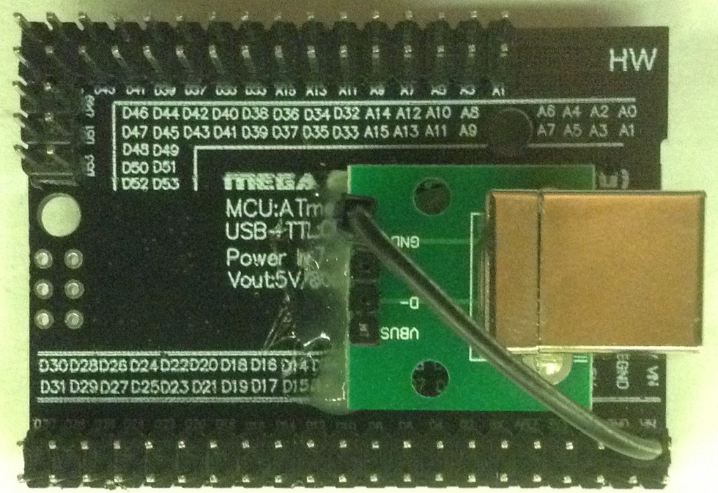
The IO connectors have all changed though to make the physical building of the module a lot easier. Here is a pin-out diagram for the Pro Mega 2560 for this panel.

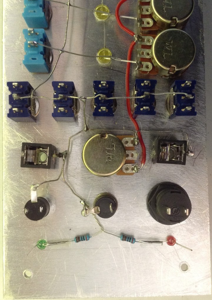
There is no PCB for this one – it is basically just panel connections and the Pro Mega 2560 – that’s all! Any additional components, such as the resistors for the LEDs or MIDI and so on, are mounted on the panel components as shown (roughly) below.

So to reiterate, the following connectors will be required to hook up the panel to the microcontroller:
- 8-way link to the potentiometers.
- 8-way link to the sequencer switches.
- 8-way link to the sequencer LEDs.
- 10-way link to the five “mode” switches.
- 5-way link supporting the GATE sockets and button, the MIDI out, and the MIDI LED.
- 1-way link for the tempo control.
- 2-way link for power and ground.
I’ve linked all the 5V and GND connections on the panel together, so only one power/ground link is required. However it will also need a way to get 5V from the external USB power to the power socket, to then be fed back to the microcontroller via its 5V pin.
This last step is optional – if you want to power it directly from the micro-USB socket on the Pro Mega 2560 you can, but I wanted a power switch on the front panel, so I’m using a USB B socket breakout (like I used in the Universal Synthesizer Panel).
The Panel
Here are a few photos showing the general design of the panel (note: only two out of eight steps of the sequencer are shown).

I’m not going into the detail of the mechanical side of the build – it is not my strong point and I am very definitely no expert. I’ll just reiterate some common sense warnings:
- Use the right tools for the job.
- Use the appropriate personal protection.
- Always secure your work area and work items – especially ensure you clamp your panel when drilling!
- Use pilot holes.
- Don’t forget some mounting holes.
For more details, see Vertical Modular Synthesizer – CD Rack Format.

There were a couple of mistakes I made when drilling the panel. One, was following the wrong vertical line for the first “mode” switch, but I realised before going right through, and figured this would be hidden by the nut for the switch.
The second one was using the wrong horizontal line for the bottom switches, but I decided that could be turned into an opportunity – I used the holes to add a MIDI LED, move the power LED and thus allow space for a future “GATE OUT” socket where I’d originally planned the put the original power LED.
This final result is what you can see in the photos that follow, but that is why they turned out slightly different to the cardboard mock-up I started with.
The Build
The general build order was as follows:
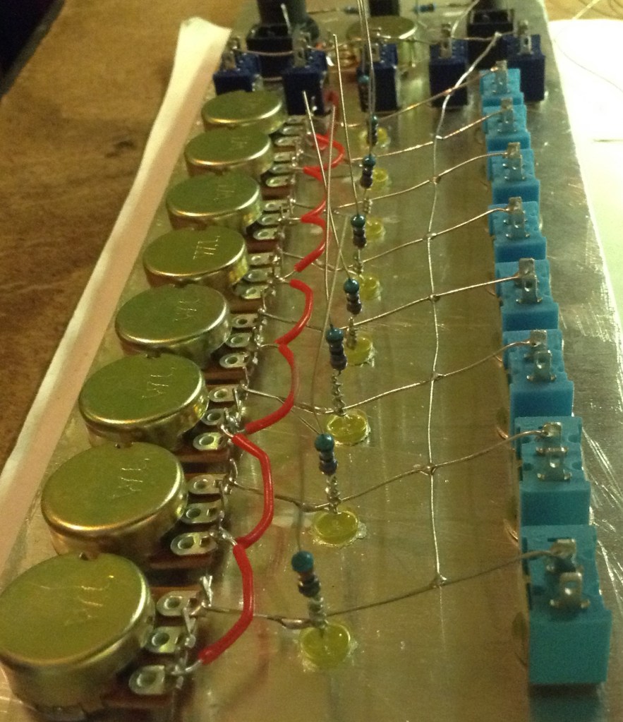
- Add the main components to the panel – pots, switches, connectors, LEDs – and fix in place.
- Add the common ground connections.
- Add the common 5V connections.
- Add the rest of the “panel-bound” circuitry (e.g. resistors for LEDS and so on).
- Add pin headers to the microcontroller.
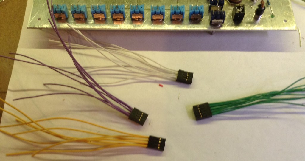
- Make the sets of connecting wires for the microcontroller.
- Connect the connecting wires to the panel.
- Sort out the power connections.
- Mount the microcontroller.
- Test, check, verify by eye and with a meter before switching on!
Here are some photos showing the various stages of the build starting with mounting the components to the panel.


The common ground and power connections follow.

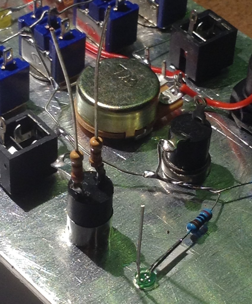
Followed by the panel-mounted resistors – there is one for each LED. In the case of the power and MIDI LEDs, I’ve tied the cathode to GND via resistors. In the case of the sequencer LEDs, I opted to connect the anodes via a resistor to the microcontroller and tie their cathode directly to GND (it made the wiring simpler).
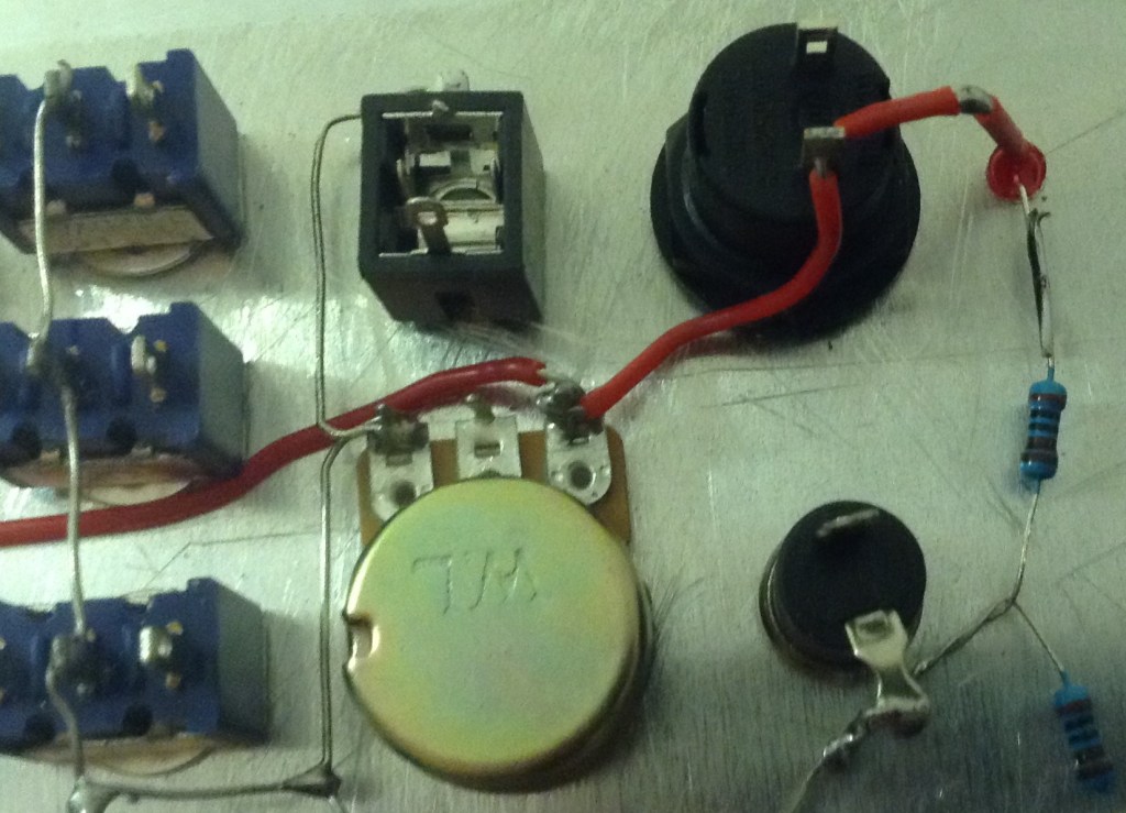
There are a few more panel-mounted links required: hooking in the power switch and 5V connection to the power LED; and the two resistors for the MIDI socket.
At this point I soldered pin headers to the Pro Mega 2560 and created the connecting cables for the main sequencer controls. Once again I’m using diy-crimped “Dupont” style headers (more details here) which will plug into the microcontroller’s pins which are soldered as if the board will be plugged into something – i.e. the long pin side is on the underside of the board. You can also see below how I’ve “hot-glue-gunned” a USB B breakout onto the underside of the Pro Mega – this will be my main “power in” that gets routed off to the panel power switch then back to the microcontroller.
The connections for the MIDI link and GATE controls and signals is slightly different – it is a single row, five-way header. Note that it is assumed that all power and ground signals are already on the panel, so this just has to support the other signals. The five-way header is wired as follows (refer to the Mega pin-out diagram above):
MIDI OUT – MIDI LED – GATE BUTTON – GATE IN – GATE OUT
As mentioned previously, these are not yet proper GATE connections – but I’ve wired them up for now directly to the 2560 so I can do some microcontroller-based triggering if I want to. THESE CANNOT BE USED AS PROPER GATE SIGNALS without the high possibility of damaging your microcontroller or equipment. Also, left “as is” the GATE IN signal will be left floating as an input signal if not in use, but if you are using a switched mono jack socket, you can connect the “switched” tag to GND so that when nothing is plugged in, it is connected to GND by default.
The following are also required:
- Single link for the tempo control (grey below).
- 5V and GND to/from the microcontroller (red and black below).
- 5V “IN” from the USB breakout to the power switch (orange below).


Finally if everything appears ok, the Pro Mega 2560 board can be plugged in.


The Code
At this stage I’m just running some basic code to test the main functions. Starting with a standard “pot test”.
void setup() {
  Serial.begin(9600);
}

void loop() {
  for (int i=0; i<16; i++) {
    int aval = analogRead(A0+i);

    Serial.print(aval);
    Serial.print("\t");
  }
  Serial.print("\n");
  delay(100);
}
This results in 16 numbers in a line on the serial console corresponding to the 16 analog inputs on the Pro Mega 2560. The way the board is wired up gives the “order” is as follows:
- Tempo pot = A0
- A1-7 = floating (not used)
- A8-15 = sequencer pots as follows:
- 1 (Top) = A14
- 2 = A15
- 3 = A12
- 4 = A13
- 5 = A10
- 6 = A11
- 7 = A8
- 8 = A9
In terms of the digital IO a similar test can be run. Here I’ve also linked the LEDs up to the switches so they can be tested too.
#define NUMLEDS 9
#define NUMLEDSW 9
#define NUMSW 10
int leds[NUMLEDS] = {46,47,44,45,42,43,40,41,12};
int ledsw[NUMLEDSW] = {38,39,36,37,34,35,32,33,10};
int sw[NUMSW] = {30,31,28,29,26,27,24,25,22,23};

void setup() {
  Serial.begin(9600);

  for (int i=0; i<NUMLEDSW; i++) {
    pinMode(ledsw[i],INPUT_PULLUP);
  }
  for (int i=0; i<NUMSW; i++) {
    pinMode(sw[i],INPUT_PULLUP);
  }
  for (int i=0; i<NUMLEDS; i++) {
    pinMode(leds[i],OUTPUT);
    digitalWrite(leds[i],LOW);
  }
}

void loop() {
  for (int i=0; i<NUMLEDSW; i++) {
    int dval = digitalRead(ledsw[i]);
    if (dval) {
      digitalWrite(leds[i],LOW);
    } else {
      digitalWrite(leds[i],HIGH);
    }

    Serial.print(dval);
    Serial.print("\t");
  }
  Serial.print("--\t");
  for (int i=0; i<NUMSW; i++) {
    int dval = digitalRead(sw[i]);

    Serial.print(dval);
    Serial.print("\t");
  }
  Serial.print("\n");
  delay(100);
}
I’ve defined the digital input and output pin numbers explicitly at the top, and the LEDs and LEDSW definitions also include the “GATE” button, using it to signal to illuminate the MIDI LED. All inputs as configured as INPUT_PULLUP so a “HIGH” reading means the switch is off and “LOW” means the switch is on.
Recall that the five mode switches are three-way toggle switches and each is connected to two IO pins. These are defined in the sw[] array. Pushing the switch “up” will set one of the pins to LOW. Pushing the switch down will set the other pin to LOW. Leaving the switch in the middle means both pins are left HIGH.
The following code can be used to quickly test the MIDI output.
#include <MIDI.h>

// This is required to set up the MIDI library.
// Tell the MIDI library which serial port to use.
// For the Pro Mega 2560:
//   Serial1 = TX/D18, RX/D19
//   Serial2 = TX/D16, RX/D17
//   Serial3 = TX/D14, RX/D15
MIDI_CREATE_INSTANCE(HardwareSerial, Serial3, MIDI);

int midiled = 12;

void setup()
{
  pinMode(midiled, OUTPUT);
  MIDI.begin(1);
}

void playNote (int midinote) {
  digitalWrite (midiled, HIGH);
  MIDI.sendNoteOn(midinote, 127, 1);
  delay(300);
  MIDI.sendNoteOff(midinote, 0, 1);
  digitalWrite (midiled, LOW);
  delay(200);
}

void loop()
{
  playNote (60);
  playNote (62);
  playNote (64);
}
This will need something receiving on channel 1 to be connected.
At this stage I’ve done nothing with the temporary GATE signals, but this should prove that the majority of the panel IO is working ok.
Closing Thoughts
I’d really like this to be able to respond to an external clock signal via the GATE IN and ideally generate some kind of clock signal on the GATE OUT, but whilst I can hook up microcontroller pins directly to clocks and signals for a bit of general messing around, to have the unit really respond to any kind of useful GATE signal it needs to cope with whatever an external source might throw at it.
In the real modular synthesizer world, GATE signals come in a variety of forms, are a range of voltages (most more than 5V, including negative) and the Arduino shouldn’t be asked to sink or source signals like this without adequate protection, isolation, and buffering. This is a whole topic in and of itself and one I might return to at some point (there is quite a good thread on the topic here).
But for this module, the next stage now is to port over the Multi-Mode MIDI Step Sequencer to the panel and add in the new functionality for the fifth mode switch, and maybe the temporary GATE signals. This is what I’ll cover in part 2.
Kevin
