I have a number of microcontrollers now that use 3.3V logic:
So far, I’ve look at MIDI OUT functionality, so now its time to look at MIDI IN, based on the circuit from my Simple MIDI Monitor. This project shows how to build your own MIDI IN circuit, but if that is too much trouble, there are some Ready-Made MIDI Modules that are 3.3V friendly too (e.g. the Hobbytronics one).
Warning! I strongly recommend using old or second hand equipment for your experiments. I am not responsible for any damage to expensive instruments!
These are the key tutorials for the main concepts used in this project:
- Getting Started with the Raspberry Pi Pico: Inputs and Outputs
- Adafruit Circuit Playground Express Tutorial
- Notes and Volts MIDI Circuit Analysis
If you are new to microcontrollers, see the Getting Started pages.
Parts list
- Raspberry Pi Pico or Adafruit Circuit Playground Express
- Either: 3.3V compatible Ready-Made MIDI Module; Or:
- H11L1 (or 6N138 – see notes) optoisolator
- 1N914 diode
- 1x 220Ω resistor
- 1x 470Ω resistor
- 4.7k resistor (for 6N138)
- 100nF capacitor (desirable)
- 5 pin din socket
- Breadboard or stripboard and jumper wires
The Circuit
If you are using a ready-made module, naturally you can skip this part. This DIY circuit is basically the same circuit as used for 5V microcontrollers.
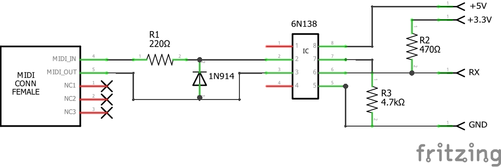
Version 1:

Version 2:
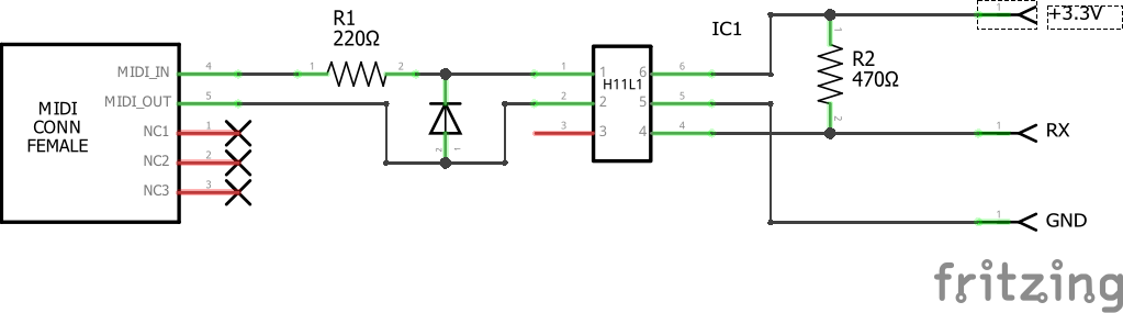
It is desirable to also include a 100nF ceramic capacitor between the power and GND pins of the optoisolator, but for simple experiments the circuit will work without it.
Update: Here is a link to a full MIDI IN/OUT circuit for 3V3 use that I’ve build onto a custom PCB: 3V3 MIDI Module PCB. This is my “go to” circuit these days 🙂
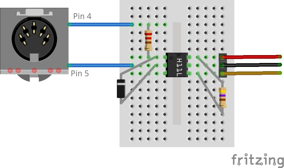
The “top” link in the diagrams is to pin 4 on the MIDI connector and the bottom link to pin 5. To help work out which is which, see the MIDI Connections Cheat Sheet.
Version 1 of the circuit used a 6N138 as that is what I had around at the time, but there seems to be a bit of divided opinion as to how well this works with 3.3V systems. The second version uses the H11L1 which seems to be preferred for 3V operation. Here are a few things to note:
- First, the actual MIDI side is independent of the supply voltage for the microcontroller. The MIDI specification for a MIDI IN deliberately isolates the MIDI side from the processing side, so the MIDI side (a 220Ω resistor and diode) is the same as 5V operation.
- The 6N138 isn’t really specified for 3.3V operation, even though a lot of circuits on the Internet seem to still suggest it can be used. It certainly seems best when still powered with 5V. The recommendation is to use the H11L1 (or H11L2) instead. Using these parts will also save a resistor!
- Some optoisolators might work with a 3.3V power supply, but many published 6N138 circuits (from those “in the know”) require a 5V supply even if 3.3V logic is required. It hasn’t been clear to me from reading datasheets why this is the case. So, note:
- My own 6N138 does indeed seem to work fine powered from a 3.3V supply – i.e. both the orange and red in the first circuit connected to 3.3V – which means I only need one power link to the MIDI board.
- “Official” circuits from those that know what they are doing (i.e. those in products) either use a 5V supply to the 6N138, so need both 5V and 3.3V, or use the H11L1 with a single 3.3V supply.
- Feel free to see how you go if you wish, but remember the warning!
- There is a pretty major discussion of some of the issues around using different optocouplers and 3.3V MIDI circuits here.
- The connection to the RX pin needs to be pulled HIGH to 3.3V regardless of what optoisolator you are using, whereas for 5V microcontrollers this would typically be pulled HIGH to 5V.
- If you get things wrong and end up putting 5V into your 3.3V IO pin you will damage your board, so once again, remember the warning!
There is a great explanatory tutorial of how the circuit works at Notes and Volts. This is described for 5V operation and an Arduino, but the principles are exactly the same here.
They key feature we need to know here is that when the optoisolator is inactive (when TX is HIGH, i.e. logic state 1), the pin 6-RX junction is tied HIGH via the pull-up resistor to 3.3V. But when the optoisolator is active (logic 0 from the transmitter), the pin 6-RX junction is connected to pin 5 which thus ties the microcontroller RX Pin LOW. The critical part for this discussion is choosing the pull-up resistor as this is required to limit the current going through the optoisolator.
Typically, output current seems to often specify a maximum of tens of mA (you might need to check the data sheet for the exact make and type of optoisolator you are using, typical values for a 6N138 are around 60mA). Now, once again I have to say I am not an electronics person, but I believe this is the critical value here for us, so we need a pull-up resistor that keeps this current below this value. So far I’ve see values of 270Ω, 470Ω and 1k used here in circuits I’ve found whilst researching.
I went with 470Ω as I’ve seen it used on the official MIDI interface circuits for the Adafruit MIDI Feather Wing and the Teensy microcontroller (v3 onwards). With a 3.3V supply this means there is a current of around 7mA. We should remember that as well as not being too high for the optoisolator, this also has to be sourced via whatever is providing our 3.3V supply, which will probably be the microcontroller.
Here is how we connect this up to the Raspberry Pi Pico then using the “version 1 circuit”. Note this is using the second UART (UART 1, not UART 0) so it connected to the RX pin on GP7. I’m pulling 5V from the VBUS pin which will be 5V when USB powered (although as mentioned above, it looks like I could get away with just using the 3.3V supply with my specific 6N138, although this is not to be recommended). Remember, if you manage to get 5V connected to a 3.3V pin, you will break things!

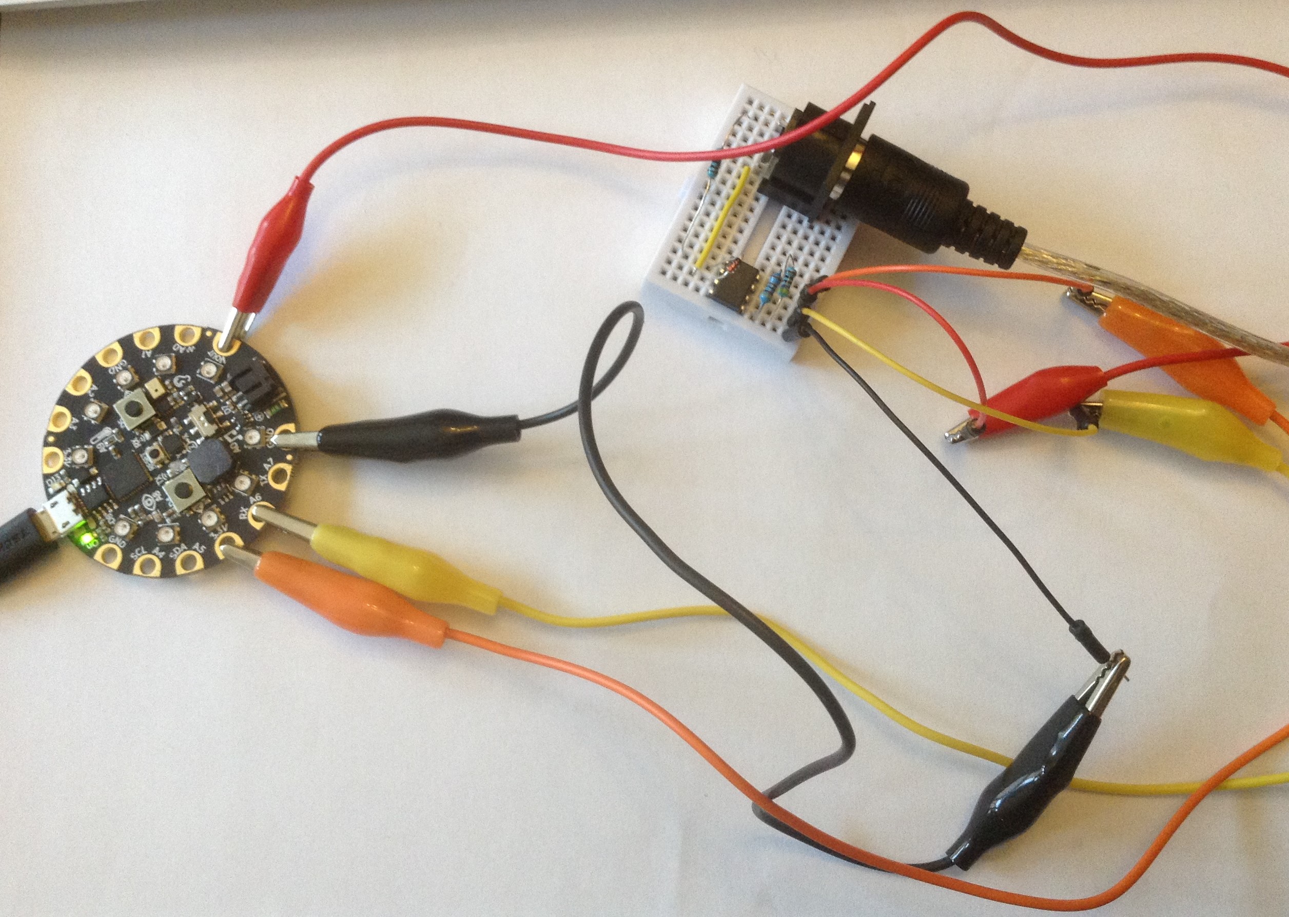
And here is how to connect it up to the Adafruit Circuit Playground Express using version 1 of the circuit. Once again, 5V comes from the VOUT pin which, when USB powered, is 5V (again, mine also works with just the 3.3V supply).
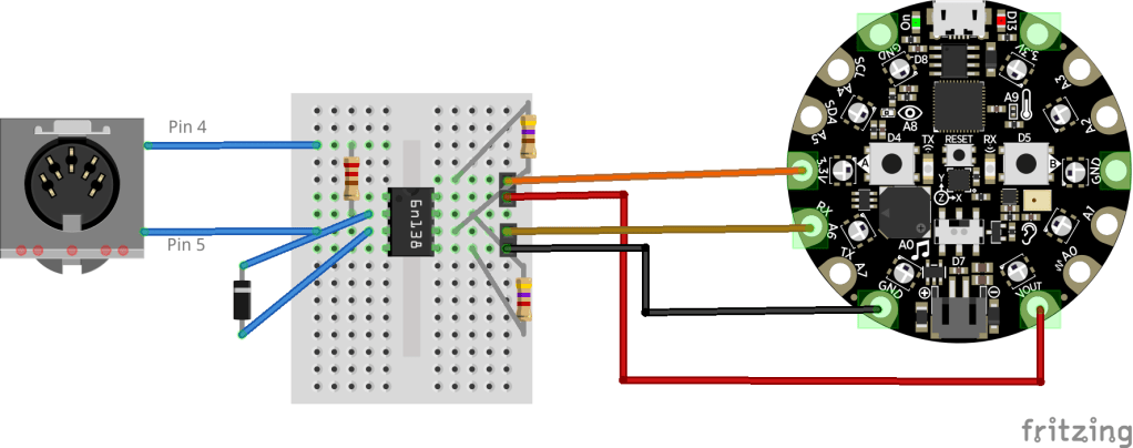
Recall the “top” link in the diagrams is to pin 4 on the MIDI connector and the bottom link to pin 5 (see the MIDI Connections Cheat Sheet).
The Code
There are two sets of code here, depending on what board and python environment you are using.
There is a MIDI handler library for CircuitPython, but not for Micropython. However, at the time of writing the Circuit Python release for the Raspberry Pi Pico still doesn’t support the hardware serial port (UART).
So for now you have the following options:
- Micropython on the Raspberry Pi Pico.
- Circuitpython on the Adafruit CPX (and similar boards).
By the time you read this, Circuitpython may well support the hardware serial port (UART) on the Pico, so it may be that the second example might work on your Pico too if you install the latest Circuitpython release.
Raspberry Pi Pico and Micropython MIDI
I’ve implemented a simple MIDI receiver that can support the idea of MIDI Running Status, using the algorithm described here: http://midi.teragonaudio.com/tech/midispec/run.htm
The basic idea is that I poll the UART using the uart.any() function and if there is data read it one byte at a time and pass it off to a MIDI handler function. uart.read() returns a byte object, but we are only reading one byte (length = 1), so just pass the first one into the doMidi function.
while True:
    if (uart.any()):
        doMidi(uart.read(1)[0])
The doMidi function then runs through the algorithm from the above site:
- Buffer is cleared (ie, set to 0) at power up.
- Buffer stores the status when a Voice Category Status (ie, 0x80 to 0xEF) is received.
- Buffer is cleared when a System Common Category Status (ie, 0xF0 to 0xF7) is received.
- Nothing is done to the buffer when a RealTime Category message is received.
- Any data bytes are ignored when the buffer is 0.
Once it has a complete noteOn or noteOff message it calls one of the doMidiNoteOn or doMidiNoteOff handlers to act accordingly. In my case I turn the LED on for noteOn messages and turn it off for noteOff messages. They also print to the console.
Update: I know have a “Simple MIDI Decoder” class you can just use directly. See this post for further details.
Find it on GitHub here as SimpleMidiMonitor.py.

Adafruit CPX And Circuit Python MIDI
Circuit Python has a MIDI library provided by Adafruit as part of their Circuit Python Bundle which can be downloaded from here. This supports MIDI sending and receiving. The resulting ZIP file must be expanded and the required libraries copied over to your CircuitPython device, in this case, copying the lib\adafruit_midi folder over to the lib folder on the CPX.
All the examples for the MIDI library seem to assume a USB MIDI connection, but using the library with the serial port is a relatively simple matter (once you’ve worked out the syntax) of passing in an object that implements a read(len) function as the midi_in parameter. In this case, that means the object returned from a busio.UART call.
The only quirk is that with no further instruction, the MIDI handling is very slow as the uart.read() function will block by default with a timeout of 1 second. The way to make it more responsive is to specify a much shorter timeout. In the example below, I’m using 0.001S or 10mS.
Like the Pi/MicroPython version I use the LED to show note On and note Off events, and print the received message to the console.
import board
import digitalio
import busio
import adafruit_midi
from adafruit_midi.note_off import NoteOff
from adafruit_midi.note_on import NoteOn

led = digitalio.DigitalInOut(board.D13)
led.direction = digitalio.Direction.OUTPUT
uart = busio.UART(tx=board.TX, rx=board.RX, baudrate=31250, timeout=0.001)
midi = adafruit_midi.MIDI(midi_in=uart)

while True:
    msg = midi.receive()
    if (isinstance(msg, NoteOn)):
        led.value = True
        print ("Note On: \t",msg.note,"\t",msg.velocity)
    if (isinstance(msg, NoteOff)):
        led.value = False
        print ("Note Off:\t",msg.note,"\t",msg.velocity)
Closing Thoughts
I still find it a challenge that there are two environments for these boards, and that there seems to be very little cross-over at present between them. I guess when the Circuit Python support for the Raspberry Pi Pico finally catches up with the CPX version then that might start to gain the edge over MicroPython. I do need to go and check out Adafruit Blinka… that may well eventually hold the key…
At least in hardware terms, I now have a MIDI IN and MIDI OUT for my Pico and CPX. The next stage in the hardware development will be to create some kind of plug-in-able “shield” type board for MIDI support.
Update: There are now a range of MIDI interface projects here suitable for 3.3V microcontrollers – see DIY MIDI Interfaces.
Software wise, it would be good to do something a little more interesting than just flash the LED!
Kevin

I suggest using a smaller resistor for the current source, maybe 100 ohms. At 3.3 volts 100 ohms will protect your circuits and will allow the opto isolator enough current to function correctly. 100 ohm should also work at 5 volts, but 220 ohms is the recommendation.
LikeLike
Thanks for your comment! I went with 220R as that was in the MIDI electrical specification, which describes smaller resistors on the other side’s output side if that is working at 3.3V logic (assuming I’m understanding you correctly), but as I say I’m not really an electronics person, so go with what others more knowledgeable than me tell me 🙂
Many Thanks,
Kevin
LikeLike
I can verify that the H11L1 works as shown in your diagram. However, the drawing of your MIDI jack (DIN) comes out as rather ambiguous so I wasted some time with it with the 2 pins swapped. After fixing that I saw the midi input working. Yay! If there is anything you could do to make it more clear that would help others using this as a starting point. Thanks
LikeLike
MIDI pin numbering I’m convinced will eventually do me in! 🙂 I’ll see what I can do. Thanks.
LikeLike
I’ve added a bit of text explaining the orientation of the DIN sockets and a link to my MIDI cheat sheet! Hopefully that makes things a bit clearer. Kevin.
LikeLike
As I understand it, the 6N138 is not specced for 3.3v operation so there’s no guarantees it will work in a 3.3v circuit. Some will, some won’t. Depends on the specific chip you have.
LikeLike
Indeed which is why the H11L1 seems like a more sure bet. But my specific 6N138 seemed ok, but as you say that is perhaps down the specific version and maybe even batch.
LikeLike
I’ve updated the post to make it a bit clearer I probably got lucky with my 6n138 and something like the H11L1 should be preferred. Thanks!
LikeLike
I am not seeing this issue widely so it is probably my setup, but I am having the same issue on both Raspbian on RPI4 8gb and Windows 10. When I try to run this on my Pico I get…
Traceback (most recent call last):
File “”, line 1, in
ImportError: no module named ‘board’
I have no issue with the MIDI OUT code you posted, but then BOARD is not imported. MACHINE is instead.
Could you advise? I really would like to have MIDI IN on a Pico, and eventually figure out MIDI THRU also.
THANKS!
LikeLike
Hmm. Re-reading through the post, I’ve not made it very clear!
The Pico code is built on a Micropython installation, which is the default version of embedded python supported by the Pico. The Adafruit code is for Circuitpython which is Adafruit’s own version of embedded python for their boards (and there is a version for the Pico too).
The code you need for the the Pico from this post is the code linked from GitHub – SimpleMIDIMonitor.py – not the example code listed later. Although Circuitpython has moved on a lot since this article so if you installed Circuitpython on your Pico instead of Micropython that second example might also work now (with some tweaking of the IO pins – it was written for the Adafruit CPX not the Pico).
Circuitpython uses “board”, Micropython uses “machine”. And they work slightly differently! Go figure!?
I’ll try to make that a little clearer in the code introduction! 🙂
Hope this helps!
Kevin
LikeLike
Sir I sincerely apologize! And that is what happens when you leap before you run. I read the whole page, should have at LEAST before I posted, and sure enough that was the issue.
So I moved to circuitpython and still had a few issues… with the board.TX, .RX, the LED… (just replaced it with GPxx designations). Solved all that I could see but NOW I have a really confusing error. Thonny is telling me that ‘velocity’ is not an attribute of NoteOff. And what is strange is that I found the code for velocity in NoteOff.py. So I am not sure what is happening here. Could it be Thonny? Should I try something else?
Anyway, thanks to your really fast reply here, I switched back to micropython on the client (MIDI-IN) and used your example on GitHub… and IT WORKS!!!! YA!
Thank you Kevin for your tolerance with me not reading the whole article FIRST! And thanks for your help!!!!!
LikeLike
No worries! Glad you were able to work it through 🙂 As I said, I thought the post could be clearer anyway, so I updated the intro for the code section to try to make it a bit more obvious what is going on!
Good luck!
Kevin
LikeLike