I’ve been using potentiometers quite a bit in recent projects and now have two boards that include options to link out to potentiometers to control boards too, so thought it useful to have another, smaller, breakout to make experimenting easy.

Warning! I strongly recommend using old or second hand equipment for your experiments. I am not responsible for any damage to expensive instruments!
These are the key Arduino tutorials for the main concepts used in this project:
If you are new to Arduino, see the Getting Started pages.
Parts list
- 4x 10k potentiometers – PCB mounted, “thumb trim” type (see photos)
- Right angle male headers
- Protoboard and wires
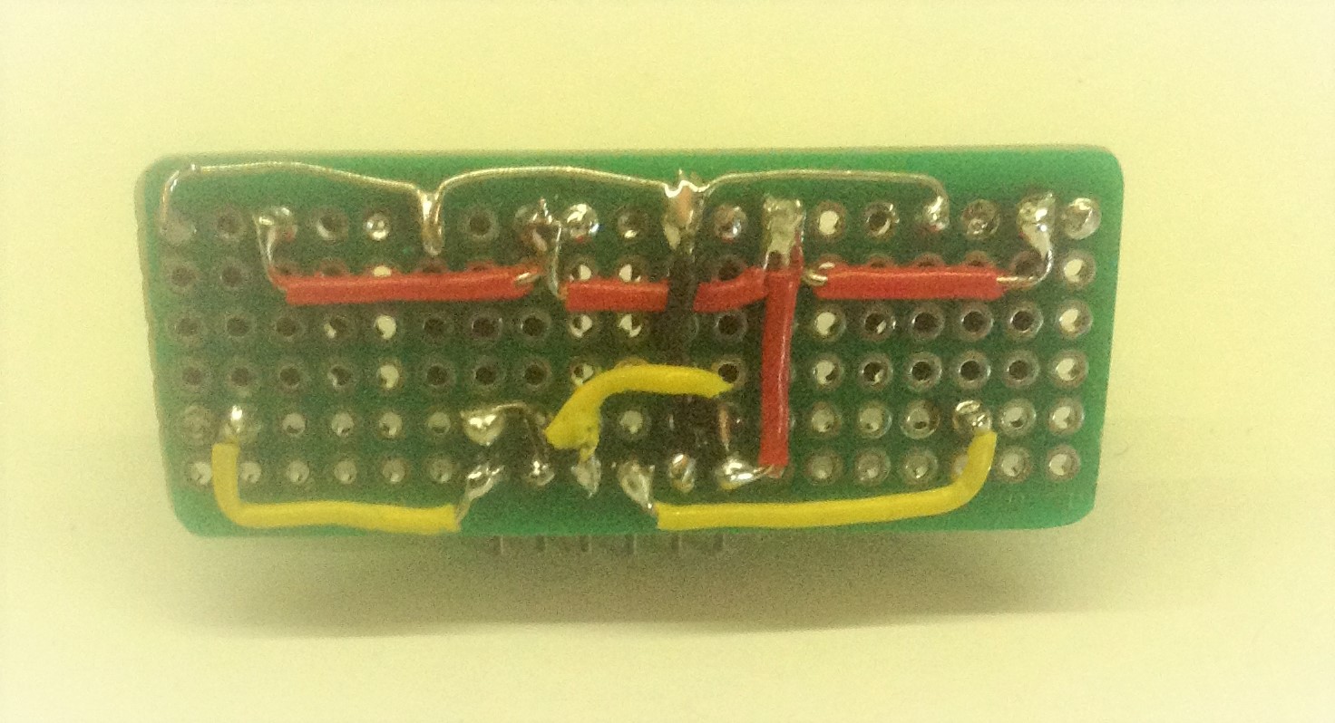
The Circuit

This is viewed from the top, with all connections assumed to be underneath. It shows four potentiometers all connected between 5V and GND and with their “wiper” pins connected out to a set of header pins.
I am using “thumb trim” type pots again, but you can use anything you have lying around – just adjust your circuit to fit!

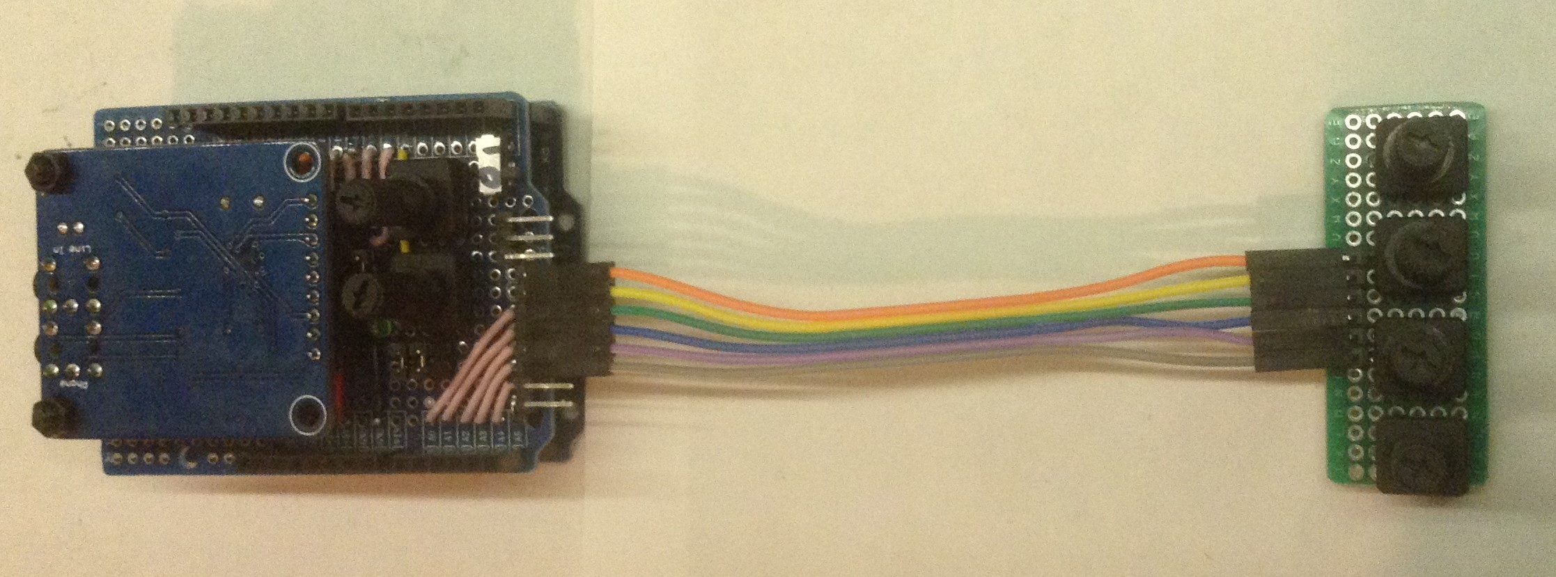
I’ve used the same orientation of 5V-GND-signals as I used on my Simple Synth IO Shield and the Arduino MIDI VS1003 Shield – Part 2 making it easy to use this as extra IO for either of them, as shown below.

The pinout also means that for quick testing, it can actually be plugged directly into an Arduino as follows:
A0 - 5V
A1 - GND
A2 - Pot 1
A3 - Pot 2
A4 - Pot 3
A5 - Pot 4
This uses the trick of using two of the IO pins as power and ground. Wasteful, but allows for simple checking that everything is working.

As with any build, check the circuit with a multimeter prior to connecting to your board. With no connections, and all pots turned full round to the same side, there should be a 2.5kΩ resistance measured between 5V and GND as there are basically four 10kΩ resistors in parallel between the two power rails. If you read zero there is a short somewhere.
The Code
I’ve not produced any synth code for this as it is an add-on, but the following is a very simple test to make sure everything is working properly.
This is coded to the connections mentioned above, where the breakout board is plugged directly into A0 to A5 on an Arduino Uno.
void setup() {
  Serial.begin(9600);

  pinMode(A0, OUTPUT);
  pinMode(A1, OUTPUT);
  digitalWrite(A0, HIGH); // 5V "supply" pin
  digitalWrite(A1, LOW);  // GND pin
}

void loop() {
  for (int i=0; i<4; i++) {
    int aval = analogRead(A2+i); // Pots on A2 to A5

    Serial.print(aval);
    Serial.print("\t");
  }
  Serial.print("\n");
  delay(100);
}
Closing Thoughts
This is a simple, but useful build and saves on a lot of solderless breadboard wiring. I could have used some of these in place of the breadboards in the Arduino MIDI Mux Step Sequencer for example and it would have been quite a lot neater!
It would be possible to include a multiplexer into the board to make a complete module accessed with the minimal number of IO pins, but then I already have a neat solution like that in the board I found here so anything else seems a little second best.
It would also be possible to link up some pots with some buttons and other IO. But again for me personally that is perhaps a little superfluous as I have another solution ready to try there. I haven’t built it and tried it yet, but I have a Synthiboard from MakerVan labs that I’m looking forward to having a play with at some point. Watch this space.
Kevin
