As part of the Arduino Multi-pot Mozzi FM Synthesis project I put together a simple Mozzi output filter circuit, but it stopped working. After having a bit of a look and poke about it it turns out that the jack socket was faulty, so I ordered a different type of socket and started again. This is the result.
- This circuit is developed further in Mozzi Output Circuit – Part 2 to add an output filter and conversion to line-level outputs.
- Also, see the official MozziByte Output Board.
Whilst this involves soldering, it isn’t a complex build so I’ve labelled it as a beginner project – that that only really applies though if you already know to solder.
This is the key tutorial for the main concepts used in this project:
If you are new to soldering, then I would recommend that you find some tutorials on the Internet to get you started soldering first.
Parts list
- Protoboard
- 1x 270Ω resistor
- 1x 100nF capacitor
- 3.5mm stereo jack socket
- Jumper wires
The Circuit
The circuit is as described in the Mozzi Output Circuit tutorial and consists of a simple resistor and capacitor low-pass filter as reproduced from the Mozzi pages below.

I’ve built two versions one for the Arduino Uno and one for the Arduino Nano. The idea is to have a simple module that connects directly to D9 and GND on the Arduino that I can plug a stereo jack lead directly into.
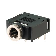
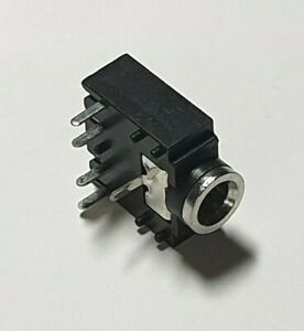
The problem with my original circuit was the socket. It was very tight getting a jack inserted and after a couple of uses the pins inside broke. I’ve bought some new ones that look like the following which seem much more robust and fit nicely into the holes in stripboard and protoboard.
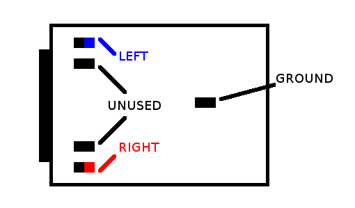
I wanted a stereo socket as I have plenty of stereo jack-to-jack leads lying around. I’ve just wired up Arduino’s mono output to both pins. Naturally it should be easy to swap for a mono jack if you wish.
The build steps for both versions for the type of socket described above, are documented below.
Arduino Uno Version
Start with a 6×6 piece of protoboard as D9 and GND on an Arduino Uno are six pins apart on the same header.

Solder on the 3.5mm jack socket then add the resistor and capacitor, linking the resistor to one of the outer socket pins and the capacitor across the same pin and the socket’s middle pin. Note that at this stage only one leg of the resistor has actually been soldered down.


The next step is to add a jumper wire between the two outer pins of the socket to connect the left and right audio outputs together.
The add another jumper wire to the GND pin of the socket (the middle one) which will hook up to the GND pin of the header when I get that far.

Now solder on the six header pins. I only actually use two in the circuit, but I’ve soldered up all six to give it a bit more structural rigidity when plugged in.
Now the other leg of the resistor can be soldered to the header pin that will connect on to the Uno’s pin D9 and the GND wire can link to the header pin that will connect to GND. I made both of these connections on the top of the board as shown below.

And here is the final module plugged into the Arduino Uno. Hopefully it goes without saying that you should visually and electrically check the board before turning things on!

Arduino Nano Version
GND and D9 are slightly further apart on the Nano, so we need a 6×9 piece of protoboard this time.

Once again position and solder on the socket then attach one leg of the resistor and the capacitor as before. Note that D9 and GND are “reversed” on the Nano compared to the Uno, so I’m sort of “making this backwards” in that the resistor will be linked to the other outer pin of the jack socket as shown below.


Now solder on the jumper wire for GND and the jumper wire to link the two outer terminals of the socket together.

I chose to use female headers for this one so that the Nano can be plugged into it directly “on top” (see the photo at the end). This means that I need the leg of the resistor and the ground wire to link up to the solder side of the headers.
So finally I solder on the headers and then can solder up the resistor and GND wires to the appropriate header pins.


And here is the final thing on a Nano. Once again, check it thoroughly before turning on.

Closing Thoughts
Having simple ready to go modules like this makes experimenting a lot easier. I might make up a few of these.
Kevin
