This is essentially a remake of my Simple USB-MIDI to MIDI but using a mini MIDI Host Shield and an Arduino Pro Mini, which I’ve not used before, with a home-made MIDI out interface to make a simple “all in one” unit.
Warning! I strongly recommend using an old or second hand keyboard for your MIDI experiments. I am not responsible for any damage to expensive instruments!
The concepts used in this project were all explained in the Simple USB-MIDI to MIDI.
If you are new to Arduino, see the Getting Started pages.
Parts list
- Arduino Pro Mini – Must be the 3.3V (8MHz) version
- FDTI or similar “programmer” board for the Arduino Pro Mini (must be compatible with the 3.3V version)
- Mini USB Host Shield
- 1x 10Ω resistor
- 1x 33Ω resistor
- 1x 5 pin DIN socket
- micro USB socket breakout board
- Long and short header pins
- Stripboard and jumper wires
The Circuit
There are three key elements to this project and assembly was particularly fiddly – to be honest, I was making much of it up as I went along!
When I purchased my USB Host Shield I noted that there was also a smaller version, so grabbed one of those at the same time. These are designed to be pin-compatible with the Arduino Pro Mini, which is a smaller version of the Arduino board originally designed and developed by Sparkfun, but now officially supported (not to be confused with the Sparkfun Pro Micro or Arduino Micro…).
It doesn’t have any kind of built-in programming support though, just a set of serial port header pins, which is why you need a separate programmer. If you want the path of least pain, I’d recommend the Sparkfun board and programmer as described in this tutorial.
Note: Do not solder any pins headers onto the Arduino yet!
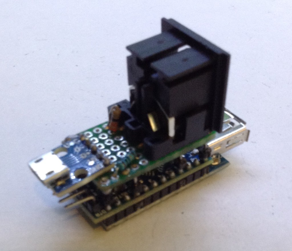
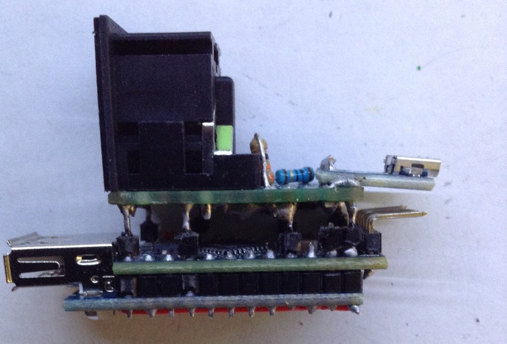
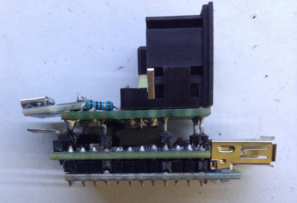
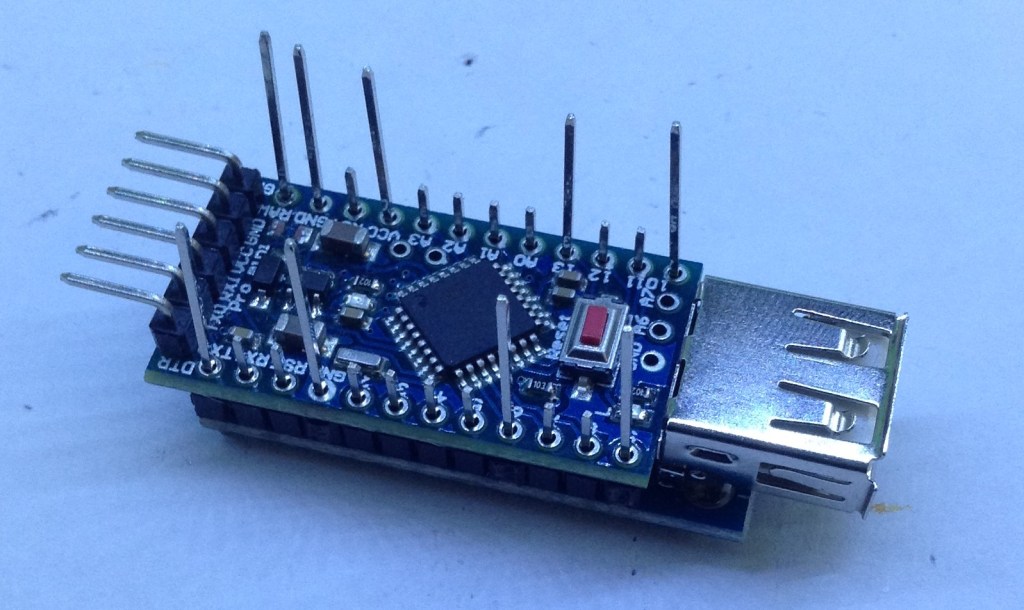
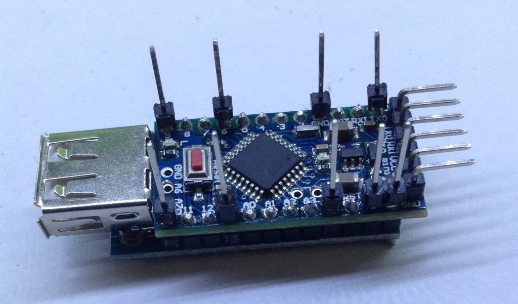
The aim was to end up with a “sandwich” of boards: the mini USB Host Shield at the bottom, and Arduino Pro Mini next and the homemade MIDI out interface on top. My final build looks like this.

First off, its worth noting that normal header pins aren’t long enough to read right through to the top later, so I used extended header pins in some places to take signals through to the home made board and to provide structural support. But I didn’t want to take all pins up as most are only needed to link between the USB Host Shield and the Arduino Pro Mini. Initially I anticipated using 9 long header pins, but eventually settled on 8. You’ll see some of the pictures below with 9 and some with 8 (I said I was making this up as I went along!)
Starting from the bottom, here’s what you need to know about each “layer”.
The starting point is the mini USB Host Shield. This will act as the starting point for soldering headers as shown in the photos below.
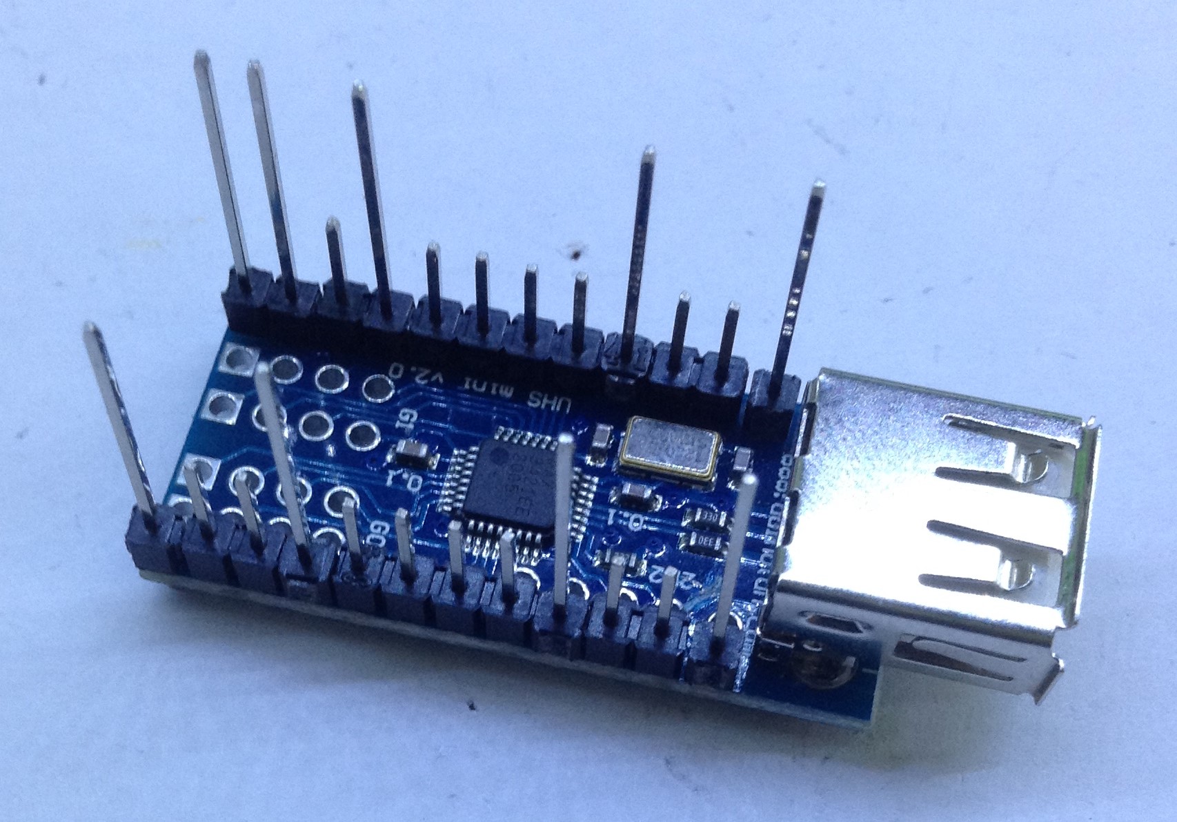
When I first put this together you can see I used nine long pins. Eventually I cut off the double long pin and left a pattern of LSSLSSSSLSSL on both sides. Note that I’ve used a header spacer on each pin too.
But there is something you need to do to the host board before you start soldering headers…
This is a 3.3V board, hence the requirement for a 3.3V Arduino to talk to it (it makes things a lot simpler!). The only issue is that USB is naturally a 5V bus, so whilst many USB devices (usually those with their own power supply) might be happy with only 3.3V VCC, my Korg microKeys, which draws power from the USB host it is plugged into, doesn’t.
Now thankfully there are several power options for the mini USB Host Shield (all documented on the original project website here) including the option of supplying an alternative power source to the USB bus itself via a “VBUS” link on the board. And the Arduino Pro Mini can easily be powered from a 5V supply by way of its “raw” power input pin which can take a range of voltage which is regulated down to 3.3V.
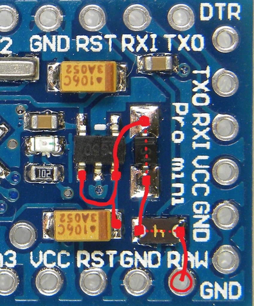
To use VBUS though you have to break the link between the USB socket and the power on the shield. Some versions of the board have a solder jumper that you an use to break the link between VBUS and the rest of the board. My cheap version didn’t so I had to get a knife and cut a track on the board as indicated in red in the following photo.

Once this was complete I soldered on the headers as described above. Then I was able to make a link between what will become the RAW power input for the Arduino and the VBUS solder pad as shown below.

Next we move to the Arduino Pro Mini.
Before fixing to the USB Host Shield, solder on some right angle headers for the 6 programming pins. Then the board can be placed on the USB Host Shield and soldered in place as follows.

Now here I hit a snag. At this point, in theory, I could load up the sketch and test the boards for USB-MIDI functionality by using the Arduino’s TX output directly into one of my other Arduino MIDI projects using their RX input.
Its worth noting that you have to be a little wary connecting 3.3V devices to 5 devices, but as this is 3.3V sending to a 5V receiver, that will work fine. In fact the definitions of “logic one” in both 3.3V and 5V land have a very similar threshold meaning that a 5V serial port will receive a 3.3V signal automatically.
Note: that going the other way might without the use of a level shifter (5V down to 3.3V) is likely to damage your 3.3V device.
You also have to be careful to use a 3.3V compatible programmer for the Arduino too. Some programmers have the option to switch between 3.3V and 5V on the board – but some only use this switch for the communications link – the power pin is still 5V! This was the case for me, so I had to wire up the programmer but connect the programmer’s 5V pin to the Arduino’s RAW pin rather than its VCC pin as part of the 6-pin programming header.
Unfortunately I had a problem. It didn’t work. After some fault finding I realised that my Arduino just wasn’t seeing any power from its RAW power pin. At this point I wondered if I’d managed to break the solder pads for the pin or something. But it turned out there was a fault with my cheap board – it actually had a component missing!
This started a real diversion, as my board has two extra components in its RAW power circuit compared to the official Arduino schematic – thankfully I had another (unused) board to compare against…
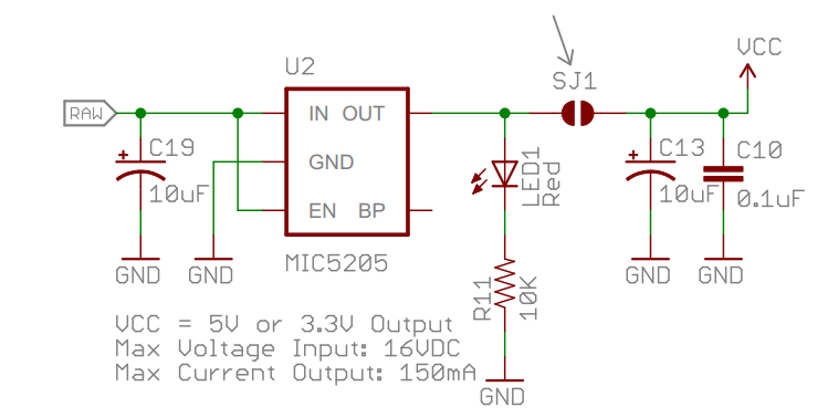
You can see there are two components (labelled “h” and “S4”) between the RAW pin and the regulator and C19 capacitor that aren’t on the schematic. It took a fair bit of Internet searching to find out that S4 is a diode and the thing marked “h” is a fuse. Apparently these add extra protection in the case of someone mistakenly powering the board via the header and RAW at the same time (I think).
Anyway, for my faulty board the “h” component was completely missing. I don’t know if it was my dodgy soldering that lost it or if it was never there in the first place. I suspect the later, as the pads looked pretty clean. Knowing it was a fuse, and knowing how I’d be using the board, I just shorted it out with solder!
At this point I could program the board and had USB-MIDI to MIDI-over-TX working fine.
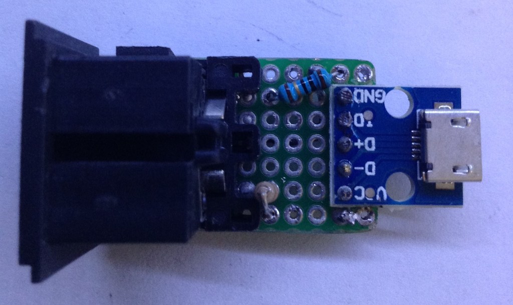
The final, and main home-made part is an Arduino Pro Mini compatible MIDI out interface which you can see here.

Each of the female 1-pin headers represents a point where the board will be soldered through from the Arduino Pro mini.
This board provides GND and 5V power to the Arduino, but then powers the MIDI interface via the TX and 3.3V power pins.
MIDI was updated at some point in its history to provide an electrical specification that can support either 5V or 3.3V operation. The main difference being different resistors in the output circuit. Remember that input circuits are opto-isolated so are independent of the transmitting circuits.
The official MIDI electrical specification says you need a 33Ω resistor between 3.3V and pin 4 and a 10Ω resistor between TX and pin 5.
I had my usual messing around with getting the right pins on the socket (my first attempt had pin 4 and 5 the wrong way round!). But eventually, this was the result.

When it came to fixing everything together, note that four of the long pins from the other two boards had to be clipped down slightly to fit snugly under the MIDI connector.
The final result is as shown at the start of this post. The whole thing can be powered using a micro-USB link to a wall socket or other USB port.

The Code
As before, the example USB_MIDI_Converter code just works out of the box for this application.
Closing Thoughts
Whilst this was quite a fiddly thing to do, it has resulted in quite a versatile little unit. If I want a MIDI TX level out, I can link up GND and TX off the programming header. If I want full MIDI, I now have that too.
This would make a nice project to put in its own box, maybe battery powered, to make a neat stand-alone unit.
Kevin

Good job! It’s funny how difficult MIDI controller manufacturers have made our lives when all you want is a simple DIN MIDI out. 🙂
LikeLiked by 1 person
need uploading program from a
Adruino IDE….?
LikeLike
That is how I tend to do most of my projects yes, certainly those involving any kind of Arduino. See the ‘Getting Started’ page for more details.
Kevin
LikeLike