In this final part of the series I present some simple configurations to show how the thing might be used.
- Part 1 – This introduction and high-level design principles.
- Part 2 – Detailed design of an ESP32 based PCB.
- Part 3 – Software design.
- Part 4 – Mechanical assembly and final use.
- Part 5 – Six simple experiments to try.
Warning! I strongly recommend using old or second hand equipment for your experiments. I am not responsible for any damage to expensive instruments!
Getting Started
The following are required to get started, assuming a fully built device (as per part 4):
- 9V battery plus battery clip to barrel jack (centre positive).
- Amplification connected to a stereo 3.5mm TRS jack plug.
- Jumper wires.
- Button.
- Solderless breadboard for further experimentation.
In the diagrams that follow, the following colour code is used:
- Knob positions: indicated by yellow lines.
- Internal wired connections: indicated by green wires.
- External wired connections: indicated by blue wires.
The starting blank panel is as follows.
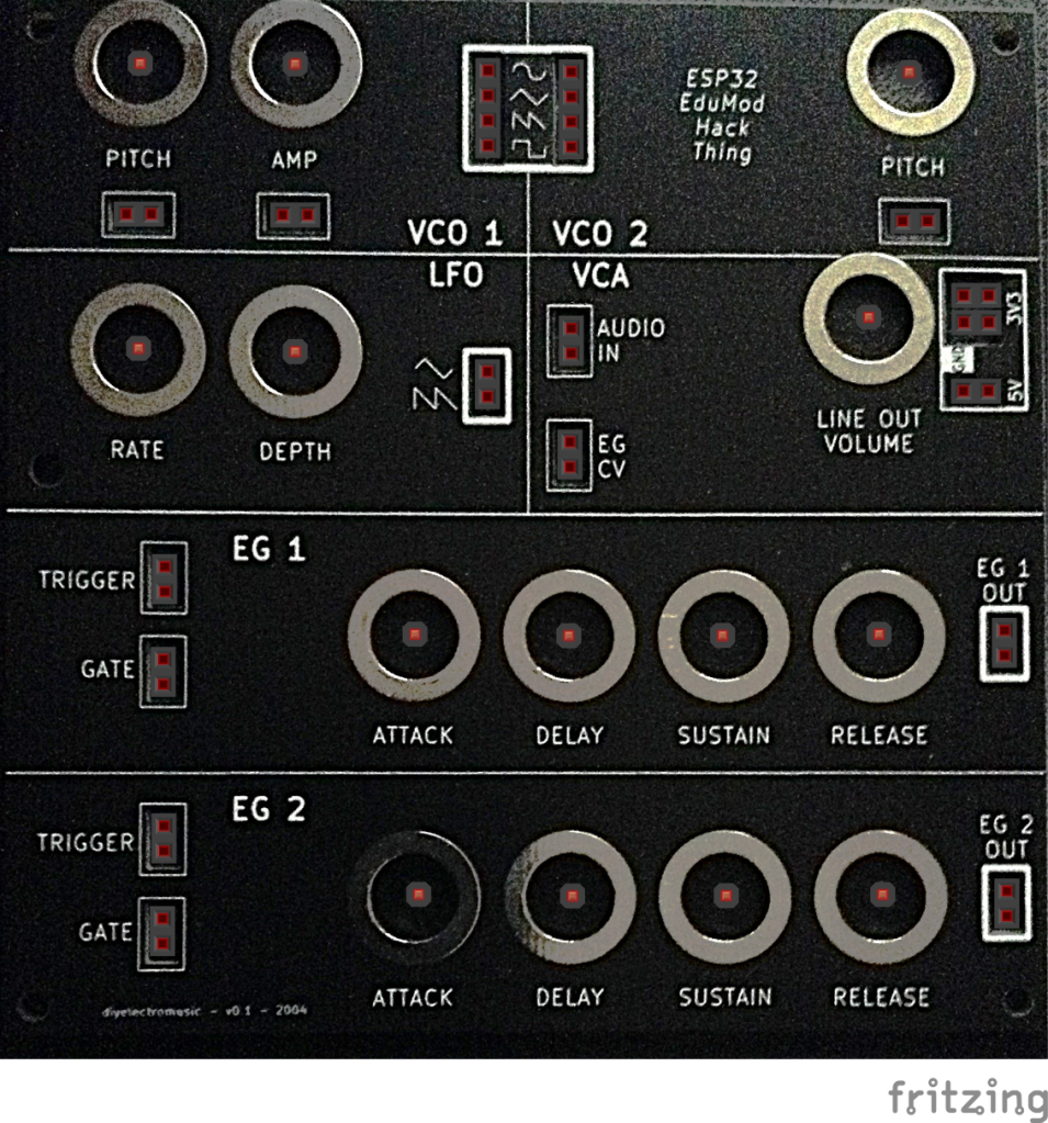
Inputs and Outputs
In general, OUTPUTs are shown with a thick border and INPUTs are shown with a thin border. The one exception are the power OUTPUTs (sorry – this was probably an oversight!).
Power Outputs
WARNING: Always double check the use of the 3V3, 5V or GND connections:
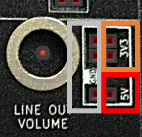
When a default “always high” control voltage is required, the 3V3 connections can be used. When a default “always low” control voltage is required, the GND connections can be used.
The 5V line is really only there for powering external devices if required. In general use it should not be used as an input to the rest of the device.
Using an Oscilloscope to Monitor Signals
One of the main goals was for the wires to be carrying “real” signals. This means that an oscilloscope can be used to monitor them.
In most cases where there are two pin header sockets, one can be used to connect to an oscilloscope to see the waveforms. The oscilloscope can be connected to one of the GND pins.
Internal signals are all in the range 0 to 3V3.
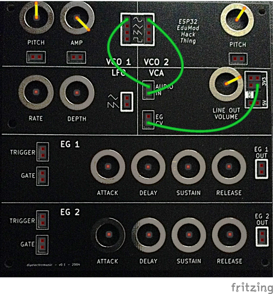
Experiment 1: Simple Oscillator Output

In this circuit one of the VCO 1 outputs is connected to the VCA and the VCA’s control voltage input comes from the 3V3 line so is “always on”.
Connect an oscilloscope to the second Audio In INPUT of the VCA to see the waveforms.
Experiment with the two VCO 1 controls and try the four different outputs.
Experiment 2: Dual Oscillator Output
This is the same as the previous circuit but the second oscillator is also patched into the VCA. The output from each oscillator individually will be slightly less as they are passively mixed together at the input of the VCA.
Experiment 3: LFO Amplitude Modulation

This is the same as experiment 1 with a single VCO but we’re now connecting in the LFO to control the amplitude of the VCO. Note that the amplitude knob must be turned all the way down for the LFO control signal to control the amplitude of the oscillator.
Experiment with the two LFO controls and try both LFO waveforms. Note that faster LFO frequencies are not as effective as lower frequencies, so go steady!
Experiment 4: LFO Pitch Modulation

This is very similar to experiment 3 but this time the VCO amplitude is once again fixed (and turned back up) and the LFO is controlling the pitch.
Experiment with combinations of the LFO and VCO pitch control. Try both waveforms and once again try small changes in LFO settings for the best results.
Experiment 5: ADSR Envelope Generation
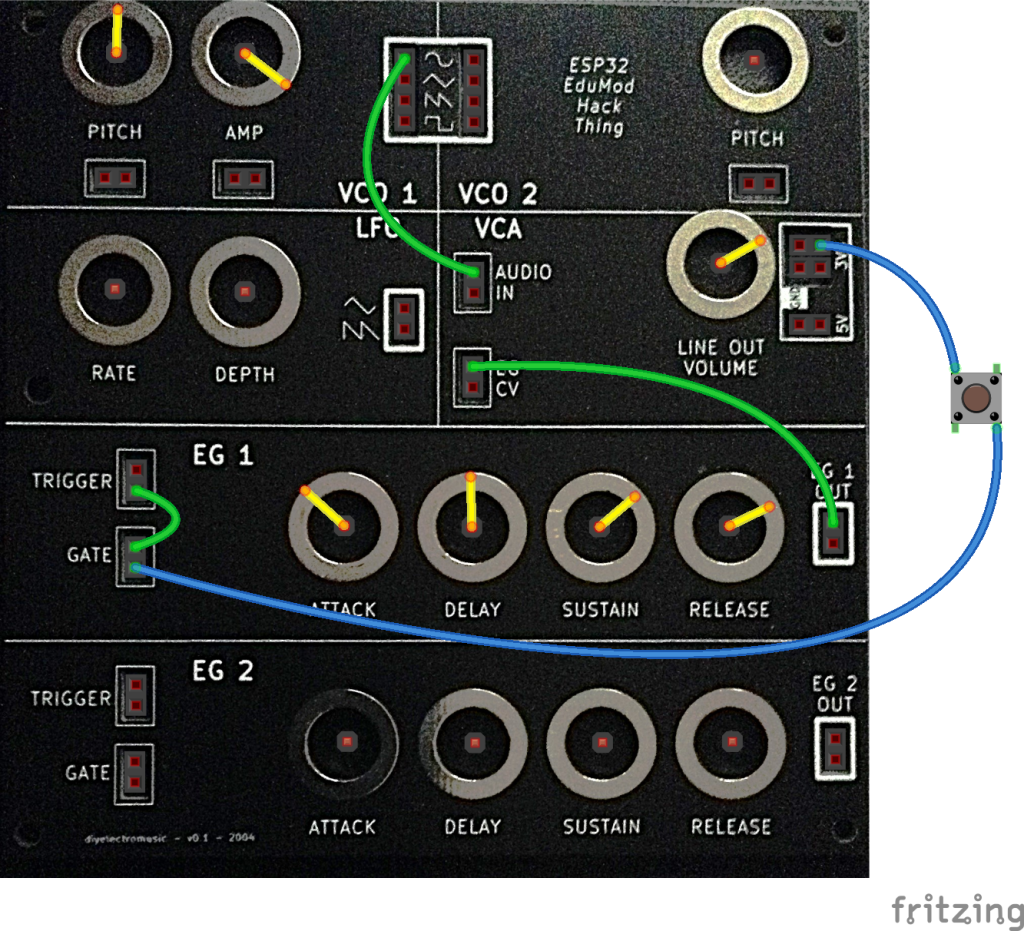
This is the first experiment to require an external component. A button is added to create a positive trigger pulse to drive the envelope generator. This can be wired directly between 3V3 and the TRIGGER/GATE input or a solderless breadboard could be used.
The EG output is now connected to the VCA control voltage input.
Note that both TRIGGER and GATE inputs for EG1 are connected together. This means that pushing the switch will TRIGGER the envelope and releasing the switch will start the final RELEASE stage of the envelope.
Initially try experimenting with a faster attack (turned anti-clockwise), a medium delay (in the middle), a medium sustain level (towards the clockwise limit), and a medium to long release (turned anti-clockwise).
If things aren’t working as you expect then it is possible that combined attack rise and delay time is too long compared to how long the button is being pressed. It is always worth testing your envelope with a long button press to ensure both attack and delay phases get to complete and arrive at the sustain level prior to the release.
Experiment 6: Envelope Generator Pitch

This is similar to experiment 5 but now the envelope generator is controlling the pitch of VCO 1 and the VCA is connected back to a continuous output.
This is a fun one to experiment with the sustain level, and some interesting “pew pew” effects can be had with short attack and delay/release times.
Experiment 7: Take Signals Off-device
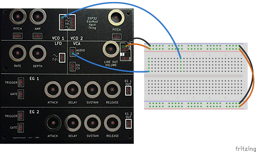
This diagram shows how to power a solderless breadboard and take signals off-device, in this case from VCO 1, and back again into the VCA.
In most cases powering the solderless breadboard from GND and 3V3 is most suitable.
In special cases a 5V supply may be required. My recommendation is to always use ORANGE for 3V3 connections, RED for 5V and BLACK for GND. This way it is much more obvious if you are about to short circuit something or use the wrong power rail.
5V signals MUST NOT be fed back into the system. There is some limited protection, but it is strongly recommended that this isn’t allowed to happen.
There is NO PROTECTION against power (3V3 or 5V) shorts to GND or connecting 5V directly to 3V3. Either occurrence will almost certainly damage something.
Closing Thoughts
This has shown the basics in action. The video at the start runs through the six experiments in order, complete with a “sigh” in the middle when I manage to knock out one of the jumper wires 🙂
Taking this further, other possibilities include:
- Getting one VCO to modulate the other – note the performance isn’t quite up to getting actual frequency modulation running, but you get some interesting aliasing effects that sound very chiptune to me!
- Using one EG for amplitude and one for pitch.
- Triggering both VCOs over MIDI perhaps with one slightly detuned.
- Adding in an external filter between the oscillator outputs and the VCA.
- Using the outputs of the oscillators to modulate an external circuit prior to bringing the signal back into the VCA.
- Using the EGs to drive external circuits that affect the signal path.
Remember that all the signals are in the 0-3V3 range, so external circuits will have to work with those voltages if the signals are to be fed back into the system. But this does mean that all signals can be monitored on an oscilloscope.
And finally, one last time, be sure to check any circuits for shorts between 3V3 and GND and only use the 5V power connection if you are using an external device that requires it – but double check it and ensure it can’t feed 5V back into the system.
Having now actually put some experiments together to show how it can be used, I’m pretty pleased with these results.
Kevin

